|
|
|
<<< Back to Results
| ||
|
Safety during a Hydraulic Work Over |
||
Country: --- | ||
Location: --- | ||
Incident Date: 5 June 2019 Time: --- | ||
Type of Activity: Drilling, workover, well services | ||
Cause: --- | ||
Function: Drilling | ||
What happened?:
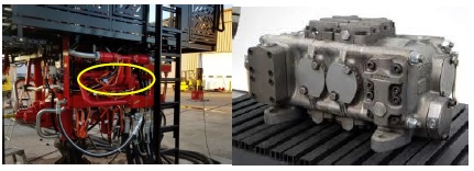
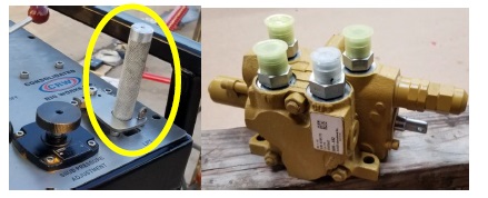
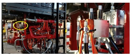
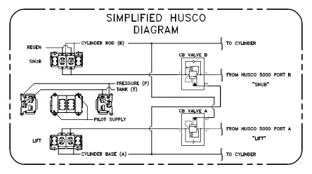
While working with an Operator to learn from a serious incident in their operations, we have identified the industry standard hydraulic control system of a Hydraulic Work Over (HWO) unit may allow the possibility for the traveling assembly to fall from a suspended position. The unintended movement of the traveling assembly does not require an energized hydraulic power unit or activation of the operator control handle. The pilot operated valve (Fig.1) which controls the primary traveling assembly of traditional HWO/Snubbing Jacks is commonly thought to be a self-centering valve which will not operate without jack supply pressure and subsequent pilot pressure signals from the associated control valve (Fig.2). We have confirmed, through testing, it is possible for the spools of the pilot operated valve to shift by way of the traveling assemblys own weight. If the trapped pressure in the lift pilot line is released, the traveling assembly will descend quickly without an energized hydraulic power unit. One method of safeguarding against unexpected traveling assembly motion is to install a counterbalance valve in the pilot circuit between the pilot operated valve pilot port and the operators control valve. The counterbalance valve (Fig. 3) should be installed as close to the pilot operated valve as possible for the best performance and effectiveness. A simplified counterbalance installation schematic is included for reference (Fig. 4). Safety is of the utmost importance to all of us in this industry. We would like to remind all operators of the inherent danger of suspended loads and the seriousness they should always be afforded. Figure 1: Pilot operated primary motion control valve
Figure 2: Operators pilot control valve
Figure 3: Pilot line counterbalance control valves
Figure 4: Simplified counterbalance installation schematic
| ||
This Industry Learning from Incident is based on, but not necessarily identical to, facts relating to a third party incident about which [the reporting organisation] has become aware. It is not provided with any warranty that acting in accordance with this document will produce any particular results with regard to the subject matter contained herein, or satisfy the requirements of any applicable federal, state or local laws and regulations. It may contain suggestions that are one, but not necessarily the only way, of addressing incident learnings. Nothing in this document constitutes technical advice if such advice is required, it should be sought from a qualified professional advisor. The following figures may not depict the exact configuration of the equipment in the field. | ||
Safety Alert number: 308
| ||
Disclaimer
Whilst every effort has been made to ensure the accuracy of the information contained in this publication, neither the IOGP nor any of its members past present or future warrants its accuracy or will, regardless of its or their negligence, assume liability for any foreseeable or unforeseeable use made thereof, which liability is hereby excluded. Consequently, such use is at the recipient's own risk on the basis that any use by the recipient constitutes agreement to the terms of this disclaimer. The recipient is obliged to inform any subsequent recipient of such terms. | ||